Introduction
There is clear, long proven evidence that spread and infection of our novel fiend SARS-CoV-2 is via airborne particles. These particles could spend up to a whole 24 hours in the air before capturing to a surface without proper filtration or ventilation. As a result we’re seeing experts encouraging more effective respirators like N95s over surgical or medical masks. The push for HEPA filters and improved ventilation in schools and other public spaces has grown immensely. One way to measure how effective a given space’s ventilation is to measure the amount of CO2 (Carbon Dioxide) in the room.
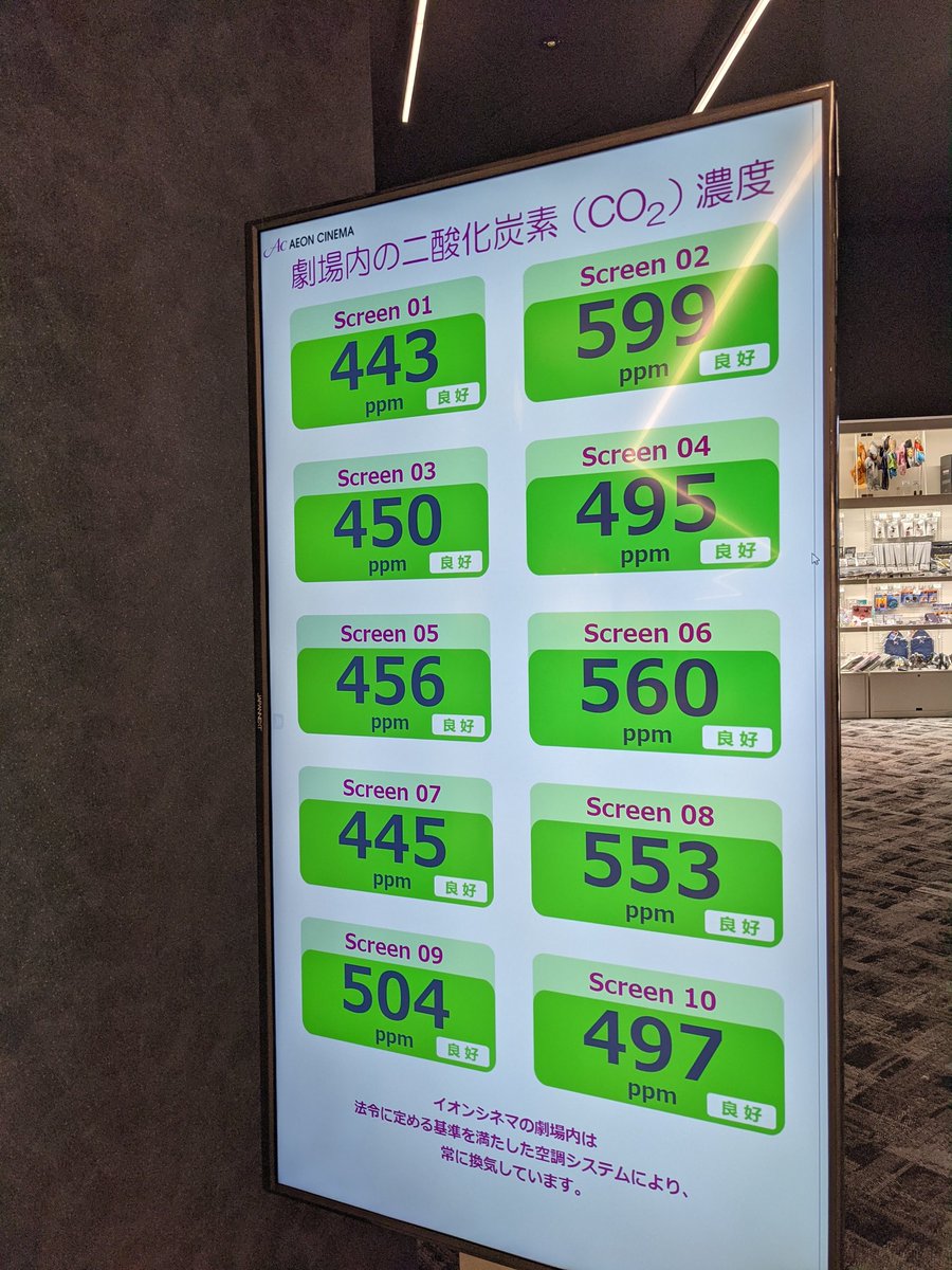
Carbon Dioxide is what we humans constantly exhale as a waste gas. It spreads easily in the atmosphere so changes in the CO2 concentration in a space is a useful indicator how well ventilated (or not) it is such as this tracking board in a Japanese movie theatre.
Through knowing the CO2 concentrations in a given space, we can make an inference that the higher CO2 concentration the higher risk to being exposed to SARS-CoV-2 and therefore contracting COVID-19.
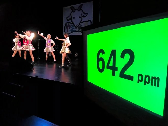
Screens showing CO2 level set up at venues to lessen virus risk
The Asahi Shimbun – Oct 23, 2020
Commercial CO2 Monitors
There’s a number of commercially available CO2/air quality monitors available including the Aranet4, but they’re generally pretty expensive (USD$200+) and as a result not accessible to the average person let alone education or the arts.
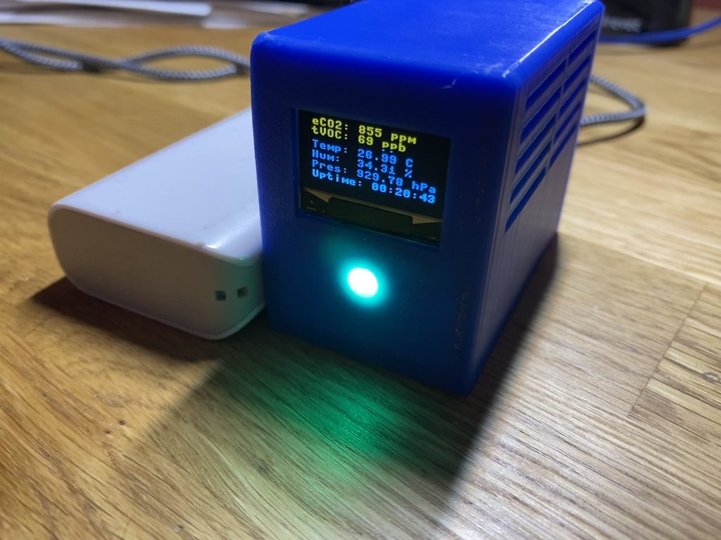
The Atmo Monitor v1
Assembly and Programming Video
Getting Started
Introducing the Atmo Monitor v1! This ultra compact device has been designed to be much more inexpensive than commercially available CO2 monitoring options and I’ve decided to open source this for educational purposes. This is in no way intended to be used as a medical device.
The Atmo Monitor v1 is based on a Raspberry Pico, a USD$4 microcontroller with plenty of Input/Output for our various peripheral sensors we’ll be attaching. The code is written in MicroPython, similar to Python 3 but optimized to run on a microcontroller.
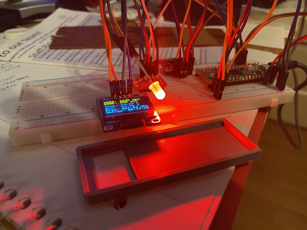
As with all my projects, I started on a breadboard. This helped me visualize the I2C bus for chip communication and the power needs along the way. All of the chips required me to solder on their header pins and using a breadboard to make sure everything was nice and straight makes it all the easier.
What to expect
Upon plugging in the monitor, the LED will be white. Once the monitor has initialized it will turn blue indicating it received its first readings from the sensors and is starting the warm up phase. This phase lasts twenty minutes.
If, within the first five seconds of starting it starts getting reasonable readings from the sensors it will switch to its operating mode. The LED will now indicate the level of CO2 being detected in your air.
| LED Colour | Description |
| White | Initializing |
| Blue | Warm Up Mode |
| Green | CO2 < 1000ppm |
| Yellow | 1400ppm < CO2 > 1000ppm |
| Red | CO2 > 1400ppm |
You may find that the sensor resets itself after a random period of time. It does this if the sensors send back a value that’s completely out of line. Rarely, and I mean rarely, the device may hang in the white or blue phase with the OLED not refreshing. Simply unplug the monitor and plug it back in.
When you first power on your monitor it’s important to let it sit for two days to allow the sensors to calibrate.
Bill of Materials
- Raspberry Pico
- ScioSense CCS811 breakout
- Bosch-Sensortec BME280 breakout
- An I2C-compatible 128×64 OLED package (SSD1306 recommended)
- Common cathode RGB LED
- Package of Dupont Wires
- 830-Point Breadboard for prototyping
- Header pins (if not included with your Pico or breakouts)
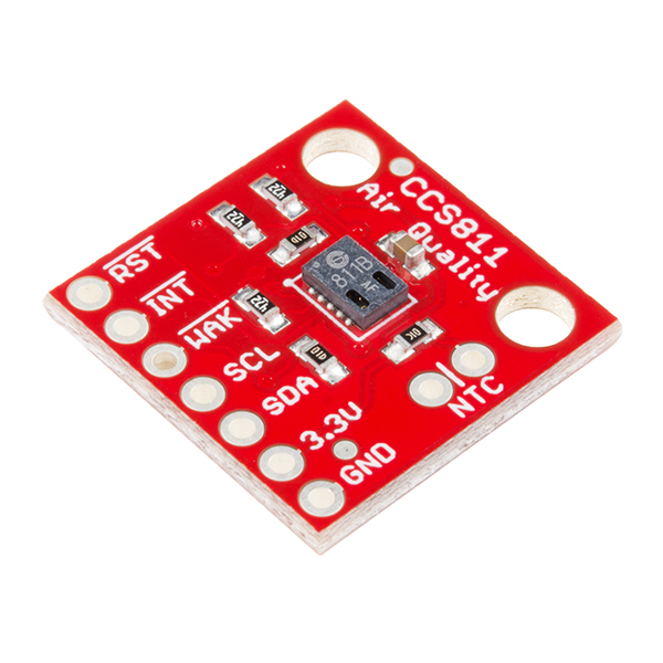
The CCS811 from ScioSense is a teeny tiny little chip that detects both CO2 and Total Volatile Organic Compounds (TVOC) that exist in the air you are sampling via what’s called a Metal-Oxide(MOX) sensor, also known as a chemiresistor.
Pictured here is the breakout board by SparkFun which made this project simpler was not cheap to ship to Canada.
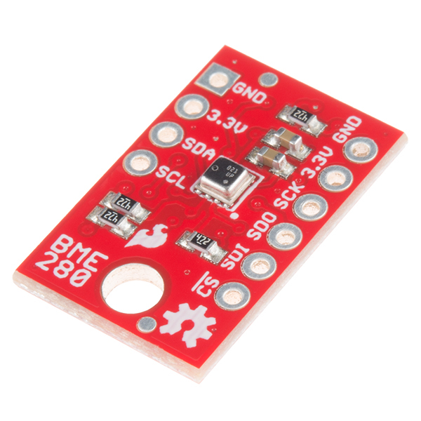
The Bosch-Sensortec BME280 is the other important piece of the puzzle. The CCS811 on its own will report pretty okay values but it’s strongly recommended to pair it with some humidity and temperature values.
Pictured here is the breakout board by SparkFun.
Where to Buy
For those in the States or are unconcerned about shipping costs otherwise, I’d recommend the boards from SparkFun. They offer the Raspberry Pico, CCS811, and BME280. SparkFun does have distributors in Canada, like Calgary based Solarbotics. I would shop around if you’re looking for these specific boards.
One thing to note about SparkFun, the OLED I purchased from them was DOA and though it’s been two weeks since I inquired with them about a replacement I have not heard back.
Otherwise, I’m stuck having to recommend Amazon. The SSD1306 OLED package I ordered had five parts and included the header pins which made the price very right. I was able to pick up both sensor boards in bulk as well.
TAKE NOTE of the arrangement of the pins on the boards you purchase as we will be soldering them directly to the PCB. If you plan to use my PCB, the GND and 3V3 pins may be swapped on the boards you’re planning to purchase and you will have to modify the part footprints and wire paths to match.
The WAKE pin on the CCS811 may be the fifth or sixth pin so the PCB allows for either. If the WAKE pin is sixth pin, do not populate the fifth pin on the breakout board.
Code
You can find the complete program plus the required libraries in my GitHub repository.
I recommend using the Thonny IDE. It makes interfacing with the Raspberry Pico very easy and helps manage required libraries pretty simple. For the libraries I include in the repo, open and save them to the Pico under a folder called libs.
It’s important to note that when you save a file to the Pico named main.py that the next time the Pico is power cycled it will automatically execute the program that exists inside that file. It’s pretty difficult to get the Pico to accept an interrupt at that point so until you’re completely satisfied that you aren’t going to make any more changes to main.py that you run the program from the Thonny IDE.
If you do end up wanting to flash a new main.py to the Pico, hold down the BOOT SEL button on the Pico while you plug it in. It will appear on your computer as a USB drive where you should uncompress and upload this file to. Unplug and hold down BOOT SEL again, return to the Thonny IDE and reflash the Micropython bootloader to the Pico. Your main.py will have been renamed main-1.py so you can continue to work with your Pico. (Thanks to the MicroPython Forum for this tip.)
PCB
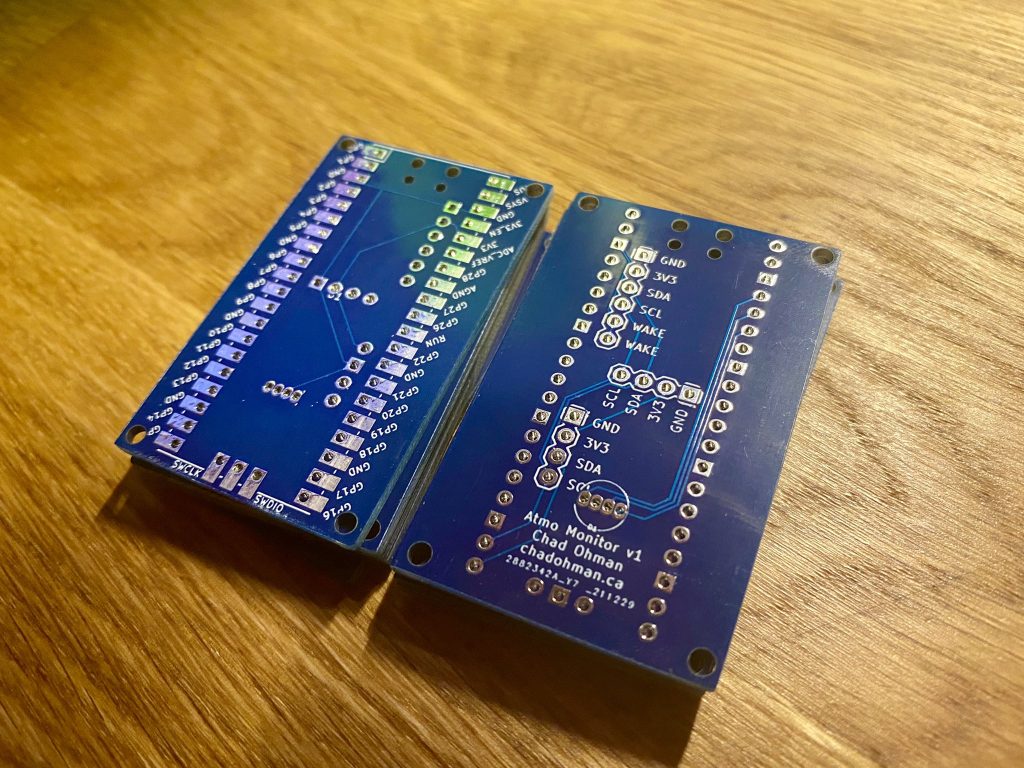
I designed the PCB in a free software suite called KiCad. The files available will only open in KiCad 6.0 and above. I use JLCPCB for the PCB construction as I’ve been very happy with them in the past with their super fast turn around time and reasonable pricing. Simply upload the Gerber files, specify your options, and they take care of the rest. Most importantly for this project (being it could end up in classrooms) is that they offer HASL lead-free finishing.
3D Printed Case
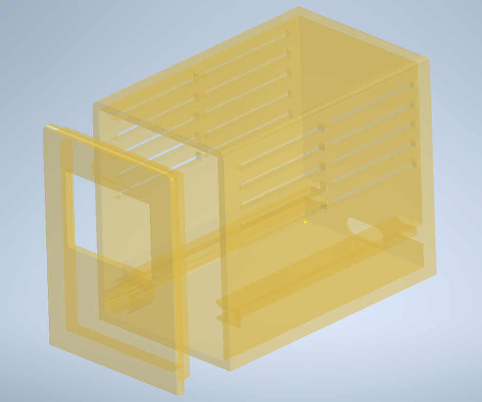
I’m in no way an expert in CAD design but I designed this 3D printed case in Autodesk Inventor. They offer discount pricing for education.
To download the STL files, find the design on Thingiverse.
MOX vs NDIR Sensors
Some familiar in this field may know that most commercially available air quality monitors use NDIR (Non-Dispersive Infrared) sensors. They use a specific wavelength of light to measure the amount of CO2 in the air. It powers a special LED on one side of the package and it collects on a sensor on the other side. When CO2 passes through the beam it absorbs this light so the sensor knows when less light is being detected by the sensor there’s CO2 present. They have a long life span, up to ten years.
Metal-Oxide (MOX) sensors measure the resistivity of specific metal compounds to test the amount of CO2 in the air. They have a tiny metal strip exposed to the air you want to test and when CO2 comes in contact it changes the chemical composition of the metal and the resistance across it changes.
Both of these sensors can be affected by temperature and humidity but the price difference and size of these two sensors is what helped me make this important design decision. I may design a version 2 which incorporates an NDIR sensor in the future but until then I’m confident the MOX sensor accomplishes what we’re going after.
License
This work is licensed under the Creative Commons Attribution-NonCommercial-ShareAlike 4.0 International License.
I have chosen this license so others can adapt upon the various aspects of it but I do not believe that others should financially benefit from it as the goal of documenting this project is to encourage others to build these to help make their spaces safer in respect to exposure to SARS-CoV-2.


